An access path is a custom route restriction, typically used to connect a marker location, a "gate" located on the perimeter of a circle or polygon marker, or a street location. The access path dictates the direction that vehicles can travel along it. This direction can be bidirectional, which allows travel in either direction along the path, or directional, which permits either entry to, or departure from, the marker to a gate or an external location on the road network.
This feature allows users to control where vehicles can and cannot enter and exit from the marker's area to the surrounding road network.
Access paths can be snapped to roads. In this case they use the existing roadways, or are manually and arbitrarily configured using the cursor. Manually drawing an access path is helpful in cases where the roadway does not exist in the map data; for example, driveways or private roads, or if you want to specify an exact custom route around a larger area such as a parking lot or depot yard.
Snapping an access path to the road
To create an access path to the closest point on the road:
| 1. | In Edit mode, right-click the purple line that links the center of the marker to the point on the road that the marker is on. |
| 2. | Click Convert to access path. |
| 3. | The purple line is converted to a bidirectional access path. Right-click the access path to make changes to it. |
Manually creating access paths
The following example describes how to create an arrival access path (including an approach gate) and a departure access path (including a departure gate) for a polygon marker that has been created over a shopping center. Approaches to the marker are permitted only through the approach gate, and departures from the marker are permitted only through the departure gate. The marker location is the depot bay entrance at the rear of the shopping center. The shopping center has several other entrances, but by configuring only two gates, the routing engine ignores all other entrances. This prevents large goods vehicles passing through entrances used by the center's customers, bypassing the main customer parking areas.

|
In this example a polygon marker over a shopping center has already been created.
|
First, add two gates:
| 1. | Click the Edit button on the Shape tab of the Marker Details dialog box. |
| 2. | Hover over the edge of the polygon. A circular marker is displayed on the blue edge, indicating that a gate can be added at the location. Right-click the blue edge at the location you want to add a gate. Gates can also be added to circle markers if needed.
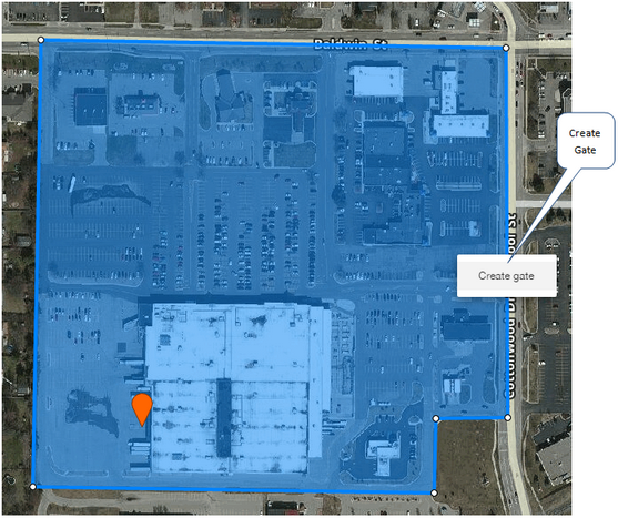
|
| 3. | Select the "Create gate" option from the contextual menu. A green gate icon is added at the location. This is the approach gate. To revert the gate back to a point, right-click the green gate icon and select "Convert to point". To delete it select "Delete gate".
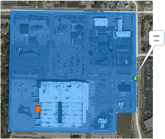
|
| 4. | Repeat these steps to add the departure gate in the upper left corner of the marker.
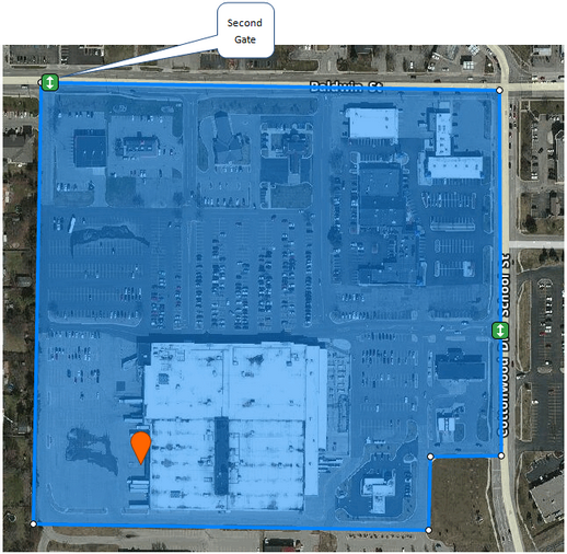 |
Next, create the access paths between the gates and the marker location:
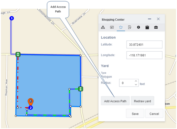
| 5. | Click the Add Access Path button on the Shape tab of the Marker Details dialog box.
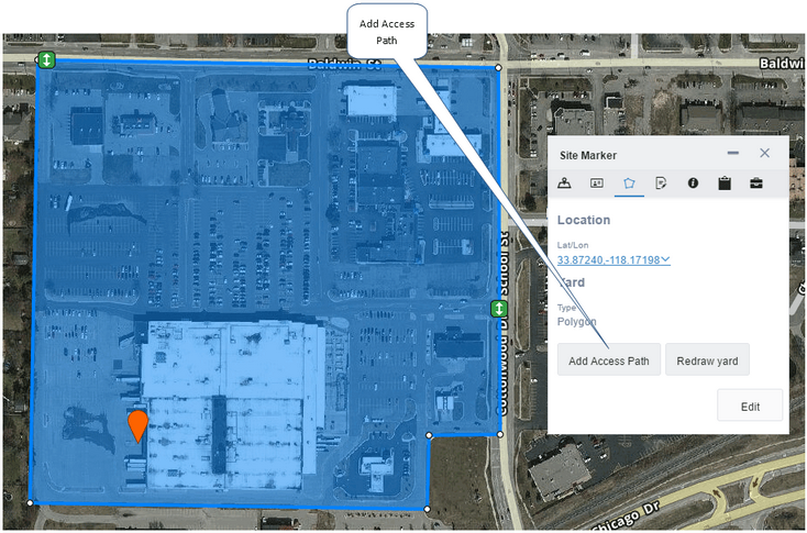
|
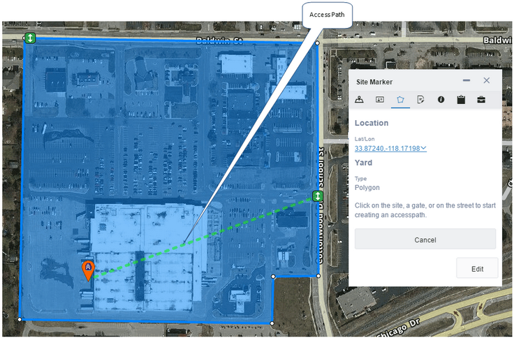
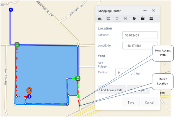
| 6. | Click the gate on the right. A green dotted line connects the gate to the cursor. The line represents the access path. You can also click the marker location pin (the orange marker in the following screenshot) first then connect it to the gate, or click a point on the road and connect to the gate, or connect the marker directly with a point on the road to bypass any gates.
|
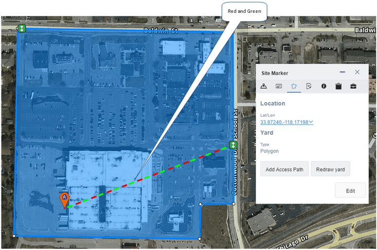
| 7. | Click the marker pin to create an access path between the depot bay entrance and the gate. The new access path is displayed as an animated green and red dotted line. Green represents a path that permits approaches only (as indicated by the direction of the moving dots). Red represents a path that allows departures only. The combination of both colors indicates that the new path is bidirectional. Travel is permitted along it in either direction.
|
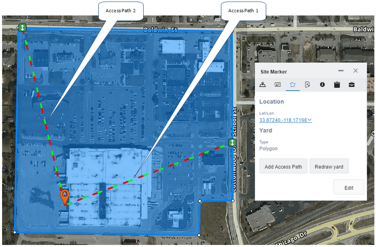
| 8. | Repeat these steps for the departure gate in the upper left corner. There are now two access paths.
|
Next, manually edit the paths so that the access paths to and from the depot loading bay travel around the edge of the parking lot, avoiding the customer parking areas
| 9. | Drag a corner or edge of the path lines to split a path into two edges, then drag the path to follow the required roadway layout.
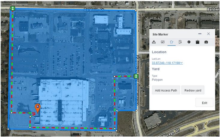 |
There are now two gates and defined access paths between the gates and the marker location.
Next, specify the direction of travel permitted on the access paths:
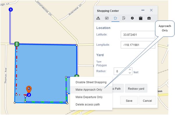
| 10. | Right-click the right path line to open a contextual menu. This is the approach path so select "Make Approach Only". The path line changes to green, indicating that this path permits only approaches to the marker.
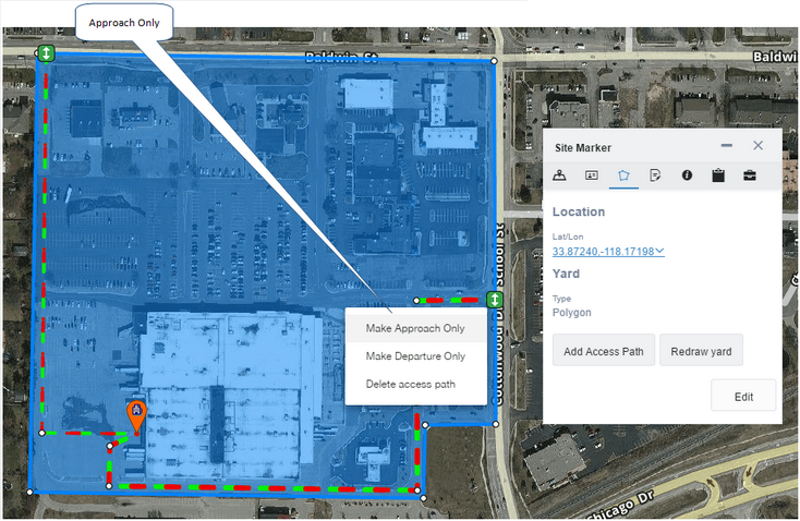
|
| 11. | Right-click the left path line to open a contextual menu. This is the departure path so select "Make Departure Only". The path line changes to red, indicating that this path permits only departures from the marker.
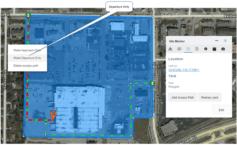
|
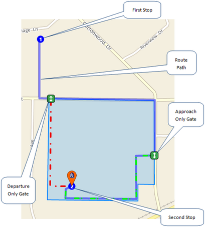
| 12. | Click the Save button on the Shape tab. Routes that include this marker as a stop will now be routed from the approach gate to the depot bay entrance, then to the departure gate when departing.
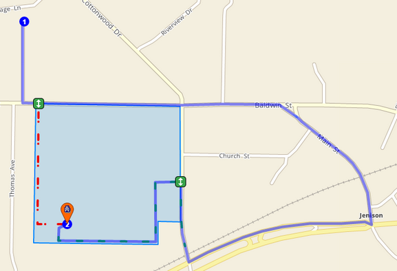
In the following screenshot a route stop has been added close to the departure gate, but the route generated ignores this gate and continues around to the approach gate, even though it is further away:
 |
Determining the approach direction
You can extend the access paths outside the marker to control the direction that drivers take on the roads when they approach or depart the marker. Routes directed to the marker shown in the previous screenshots could arrive at the approach gate from either the north or the south. You can connect an additional access path directly to the road network to restrict access to the approach gate from a particular direction. The following example describes how to restrict the arrival at the approach gate from the south.
| 1. | Click the Edit button on the Shape tab of the Marker Details dialog box. |
| 2. | Click the Add Access Path button, then click the approach gate on the right.
|
| 3. | Click a location on the road network south of the approach gate. A new access path is created between the approach gate and location you clicked.
|
| 4. | Right-click the new access path and select "Make Approach Only" from the contextual menu.
|
|
The "Disable Street Snapping" option in the contextual menu is used when there is no base map data for the access path to route along; for example, when routing along private roads. This feature allows the shape and location of the access path to be manually controlled. When street snapping is enabled (the default behavior of access paths) the access path attempts to travel along the nearest known road network, as contained in the base map data. Street snapping can be toggled on or off on a segment-by-segment basis (between each set of vertices).
|
| 5. | Click Save. When the route is generated again it will show the arrival at the approach gate from the south:
 |
|

 Changing a Circle Marker to a Polygon Marker
 Previous
 Next
Next Expand/Collapse
 Print
Print Share Page
 Training
 Knowledge


